Normally there is no need to worry about logic equivalence check in timing ECO, even though the check has to be run every time timing ECO is done. However if timing ECO flow introduces some non-equivalence failures, it's very hard to debug these failures. A real timing ECO case had the following scenario: Logic equivalence started to fail after one round of timing ECO. Hundreds of inverters and buffers had been added and some gates had driver strength upsized or downsized. It's impossible to use text diff to find the cause. While formal tool didn't give too much clue either. It only showed several failing vectors of support points.
In this use case, we will demo a new way to catch this problem by GUI mode Logic Equivalence Check.
Apparently the accidentally timing ECO change is random, it may have mis-connected a wire, or added an extra invert. In terms of circuit structure, the change maybe very small, like only one instance being wrongly modified. However, when the logic cone is represented in a formal expression, Binary Decision Diagram, for example, the result is totally different.
For example, check the support points of the selected net in the following schematic.
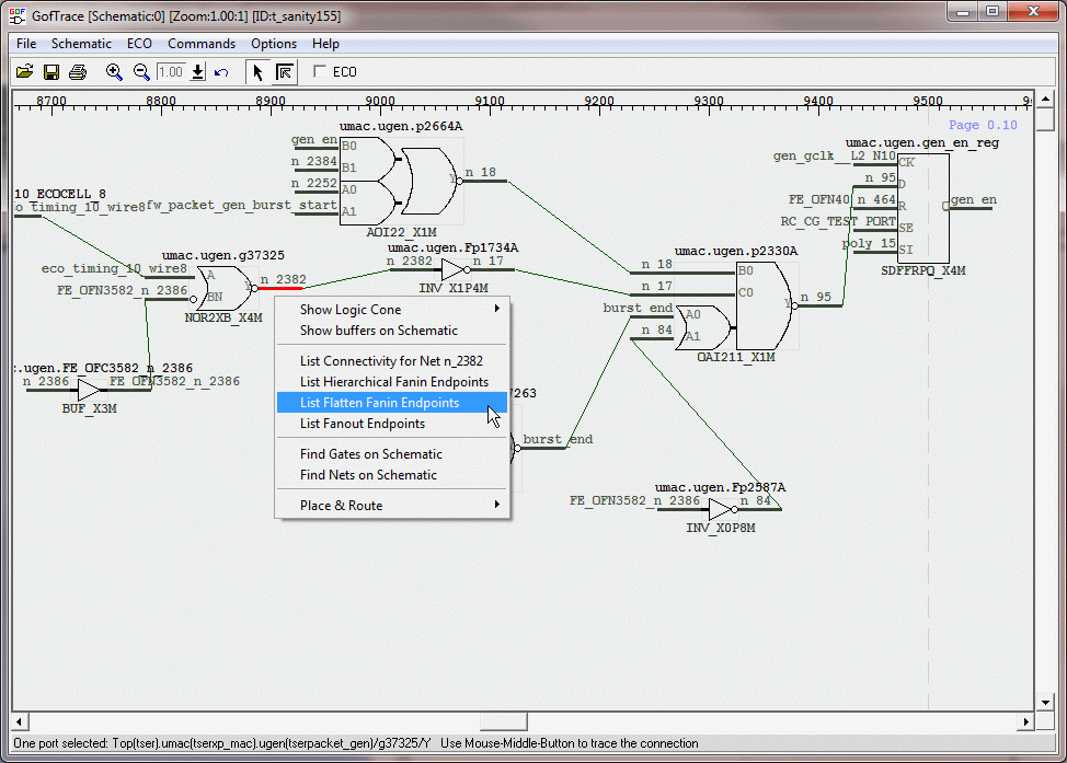
Figure 1, Find support points
It has 66 support points which are in flip-flops or input ports formats. Debug vectors generated on these support points would be hung amount and helpless for debugging.
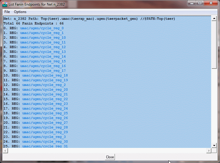
Figure 2, List support points
If a formal tool can dump internal equivalence information for each instance, we can trace the equivalent/non-equivalent information to get to the failure point. Since logic structure remains the same in timing ECO, it would be easy to compare the equivalence on the circuits.
Gates On the Fly has all internal equivalence information saved after logic equivalence is done. To do logic equivalence check on schematic, both implementation design (or called gold design) and reference design (or called revised design) should be loaded.
The command line to load both designs, "gof -lib tsmc.lib implementation.v -ref reference.v".
Once GUI window is up, load the flops under check from both designs.
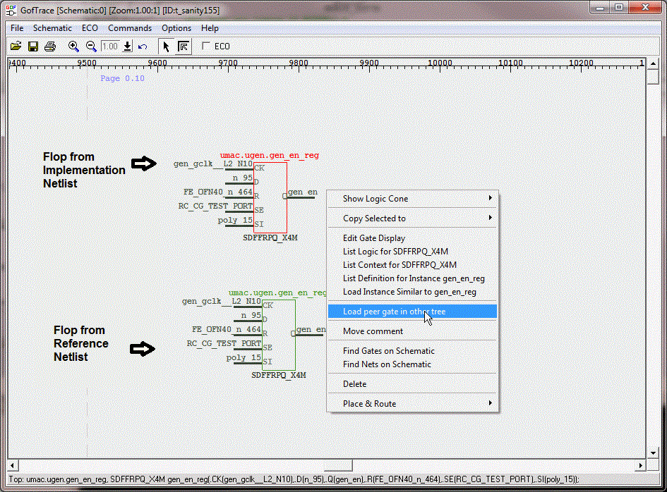
Figure 3, Load points under check
Select both D input pins of the flops. Press and hold Ctrl key, click mouse-left-button on both D input pins. Click mouse-right-button to pop up menu, select 'Equivalence Check' command.
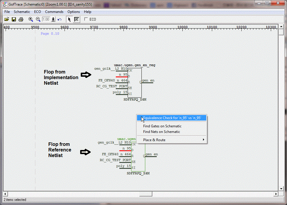
Figure 4, Run equivalence check
As we expected, the result is non-equivalent. However, all internal equivalence information has been saved.

Figure 5, non-equivalent result
Use mouse-middle-button click on input pins to trace and expand the schematic. And keep on checking the pair nets equivalence.
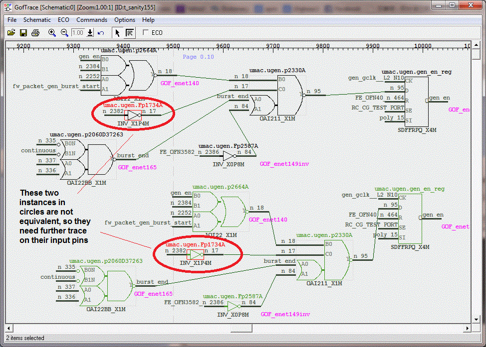
Figure 6, Equivalent information on schematic
The schematic shows extra inverter has been added by timing ECO flow, and it has odd number of inverters.
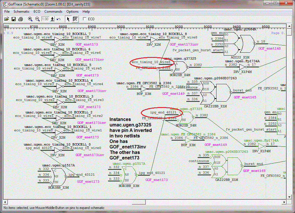
Figure 7, Locate the failing point
Gates On the Fly can do the ECO on the same schematic. Click 'ECO' button to enable ECO mode.
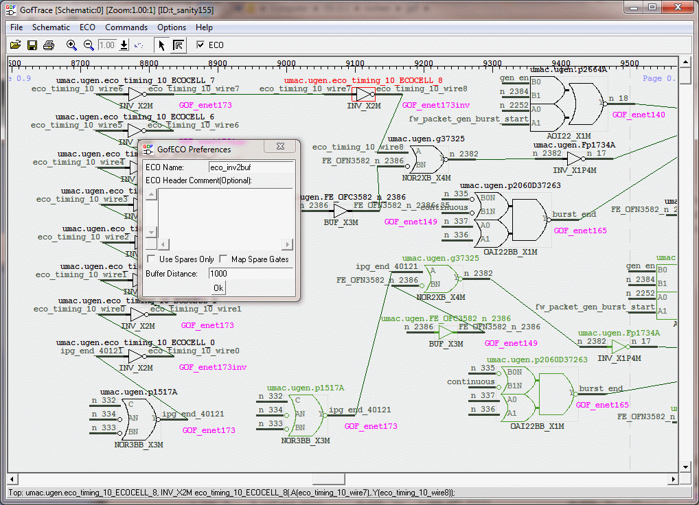
Figure 8, Enable ECO
Select 'Change Gate' command to change the inverter to a buffer.
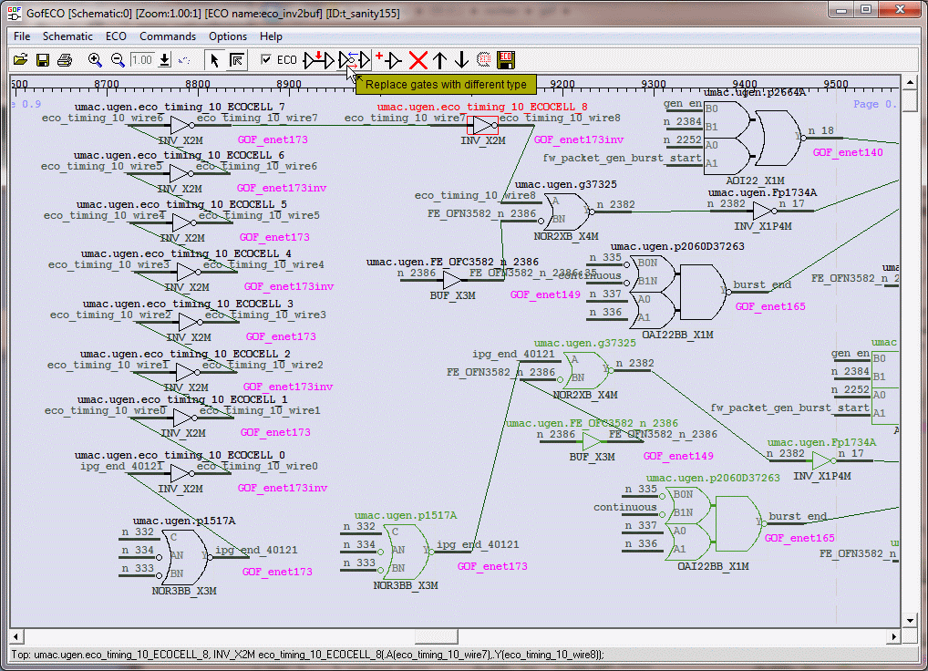
Figure 9, Run change gate command
Pick a proper buffer.
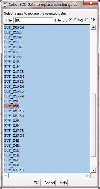
Figure 10, Pick a buffer

Figure 11, Choose pin connections
ECO is done. Save the ECO result in verilog mode or script mode.
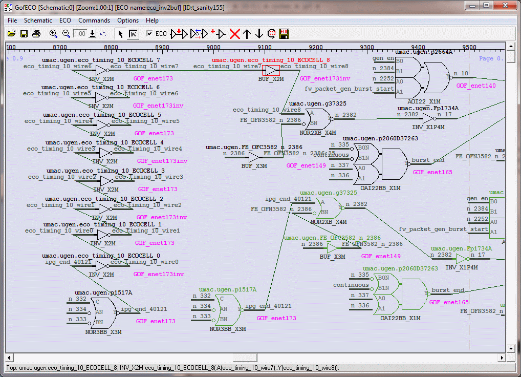
Figure 12, Final result
The ECO result should be saved before rerun equivalence check. After ECO is saved, select the D input pins of the flops and redo the equivalence check.
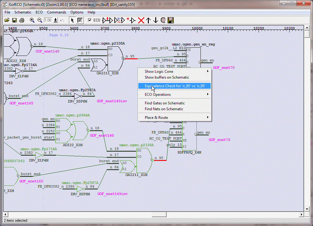
Figure 13, Redo equivalence check after ECO
The two fops have D input pins being equivalent.

Figure 14, Result is equivalent