Metal configurable gate array cells are specially developed for Metal Only ECO. These cells come in two types, which are used in different backend stages. The first type is gate array spare cells, which are typical filler or decap cells used in the original flow. During the backend P&R stage, gate array spare cells such as GFILL/GDCAP are incorporated and distributed throughout the design. The second type is gate array functional cells, which are used in post-mask ECO. Gate array spare cells are replaced with gate array functional cells such as GAN2, GND2, and GXOR2.
The base unit of gate array cell is a tile. Every gate array cell consists of one or more tiles. Use one 5nm standard library as example:
| Tile Numbers | Spare Cells | Functional Cells |
|---|---|---|
| 1 | GFILL1 | GTIE GINVD1 GND2D1 GNR2D1 |
| 2 | GFILL2 | GBUFD1 GAN2D1 GOR2D1 GAOI21D1 GDN3D1 |
| 3 | GFILL3 | GAO21D1 GAN4D1 GOR4D1 |
| 4 | GFILL4 | GINVD8 GAN2D4 |
| 5 | GFILL5 | GMUX2D1 GXOR2D1 GXNOR2D1 |
| 6 | GFILL6 | GBUFD8 GSDFFRQD1 GSDFFSQD1 |
| 8 | GFILL8 | GINVD16 |
| 12 | GFILL12 | GCKLNQD6 |
Table: Tile Numbers in Gate Array Spare Cells and Functional Cells
Gate array cells have a larger size than normal standard cells. For instance, GFILL1 is four times larger than FILL1, and GND2D1 is 25% larger than ND2D1. However, the power consumption and timing of these cells are similar.
Each gate array spare cell has a location defined by a DEF file. In Figure 1, the location of one GFILL8 spare cell is defined as (Xg, Yg), with a tile height equivalent to that of GFILL1 and a tile width eight times that of GFILL1.
GFILL8 tiles can be regrouped and rewired in metal layers to create different functional cells. For example, GBUFD1 requires two tiles and implements a buffer function, while GAN4D1 uses three tiles to create a 4-input AND function.
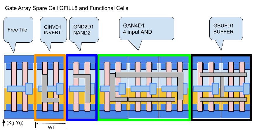
Figure 1: Gate Array Spare Cell GFILL8 Regrouped Tiles to Form Functional Cells
When generating a patch, GOF synthesizes it using only gate array functional cell types. These functional cells are then mapped to the most optimal nearby gate array spare cells with the minimum wire connection costs.
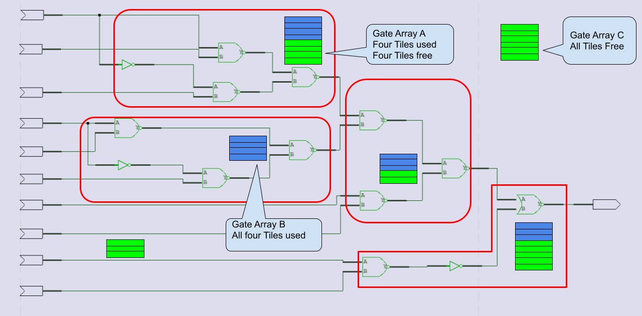
Figure 2: Gate Array Spare Cells Mapping to Functional Cells
Once the mapping and swapping process is complete, some gate array spare cells may have portions of their tiles being used by several functional cells, as shown in Figure 2. To properly save the ECO results, the type of these gate array spare cells should be changed. For instance, gate array A should have its type changed from GFILL8 to GFILL4. Any completely used up gate array spare cells, such as gate array B with type GFILL4 and all four tiles being used, should be deleted.
The mapped gate array functional cells need to be moved to the locations of their corresponding gate array spare cells, with the horizontal location X adjusted based on the starting tile location. For example, the GINVD1 instance should be moved to (Xg+TW, Yg), and the GBUFFD1 instance should be moved to (Xg+TW*6, Yg), as shown in Figure 1.
GOF writes out an ECO verilog file and backend tools ECO scripts. In the verilog file, the location of the newly added gate array functional cells is written in comments. GOF supports both Synopsys ICC script and Cadence Encounter script, both of which have cell location placement support.
For example, when saving the result in an ICC TCL script, the cells in Figure 1 would have the following commands:
Encounter script format:
Note:Tile size assumed to be 0.20 X 0.22; GFILL8 location (Xg, Yg)=(253.82, 413.28)
In the experimental design, both gate array spare cells and standard spare cells are inserted. The placement shown in Figure 3 highlights the gate array spare cells in green and the standard spare cells in red. It is clear from the figure that there are many more gate array spare cells distributed throughout the design than standard spare cells. Additionally, a gate array cell can be used as any functional cell as long as it has the same or more number of tiles than the gate array functional cell. This means that performing ECO using gate array spare cells is much easier than with standard spare cells.

Figure 3: Gate Array Spare Cells vs Standard Spare Cells Distribution
The ECO using gate array spare cells resulted in the addition of approximately 70 gate array functional cells, as shown in the design. The wire connections for these cells are concentrated in one location, as illustrated in Figure 4

Figure 4: Gate Array ECO Gates Connections Concentrating in One Area
The ECO using standard spare cells resulted in the use of approximately 90 spare gates, which are scattered over a large area, as shown in Figure 5. In comparison, the gate array spare cells ECO has a very concentrated ECO area, which is indicated by the red color in the figure. However, in the standard spare cells ECO, the utilized spare gates are spread over a large area, shown in blue in the figure.

Figure 5: Placement and Wiring Comparison of Gate Array Cells ECO and Standard Spare Cells ECO
In conclusion, based on the comparison of ECO using gate array spare cells and standard spare cells, it is recommended to use gate array spare cells ECO if possible. This is because gate array spare cells are easier to use and result in a more concentrated ECO area, which can simplify the ECO process and potentially reduce the design complexity. In contrast, standard spare cells are scattered over a large area and may require more effort to implement and verify the ECO changes. Therefore, whenever feasible, gate array spare cells ECO should be the preferred approach for performing ECO in the design process.
Check Metal Configurable Gate Array Cells ECO in User Manual for detail