GOF offers various ECO flows to cater to different netlist ECO scenarios.
One of these flows is the Automatic Full Layers ECO Flow, which can be executed using the "fix_design" command in GofCall scripts. GOF provides support for both global and incremental mode Automatic ECO. The GofCall script is Perl-compatible and utilizes exported APIs to access the netlist database. With the Full Layers ECO Flow, gates can be freely added or deleted as needed.
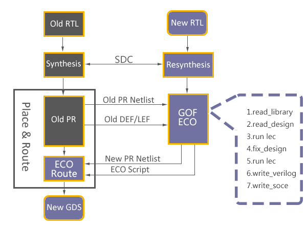
Figure 1: Functional ECO Flow
GOF offers two modes of Automatic ECO flow: global and incremental. In the global mode, a top-down Logic Equivalence Check is performed on the design to isolate non-equivalent modules. This mode guarantees logic equivalence between the ECO result and the reference netlist.
On the other hand, the incremental mode allows for faster ECO size estimation by directly specifying the modified module names in the "fix_modules" argument list.
GOF utilizes its built-in Logic Equivalence Check Engine to determine the minimum number of patch gates required to fix non-equivalent modules. For each non-equivalent module, GOF extracts all non-equivalent points and analyzes the two logic cones from the implementation and reference netlist. The Logic Equivalence Check Engine then collects all related logic in the implementation logic cone and combines it with new patch logic to fix the failing logic cone. This process continues until all modules are fixed and the implementation and reference netlists are equivalent.
Compared to other ECO tools in the market, GOF is able to produce smaller logic patches and avoid redundant fixes in good modules. For instance, Conformal ECO struggles with fixing complicated combinational logic and may require more than 30 or 40 gates for some ECOs, while GOF only requires a single-digit number of gates.
In cases where new flops are involved in the ECO, GOF offers an API to automatically stitch the scan chain. By combining the GUI ECO mode and script ECO mode, GOF achieves an optimal ECO result.
The use case "Automatic Full Layers ECO" shows how to fix a modified module automatically.
Metal Only ECO can be done automatically as well. The implementation netlist should have spare gates instantiated. A spare gate pattern is set in GofCall ECO script, GOF uses internal synthesis engine or external synthesis tool to re-synthesize patch circuit to have spare gates type only. In the end, GOF maps all spare gates to the exact spare instances.
The use case "Automatic Metal Only ECO" shows how to do automatic metal only ECO.
In many cases, the ECO operations are well known by users. They can be inserting buffers to a 128bits bus, or adding isolation AND gates to all outputs of a module. In these cases, manually ECO is more efficient and resource saving.
Manually ECO can be done in Script mode or GUI mode. GOF exports many APIs for ECO operations in GofCall script.
Key factors for successful manual ECO are fast locating the ECO spots and implementing the changes efficiently. GOF APIs serves these two key factors seamlessly. The netlist browsing APIs find instances, ports, pins or nets in a quick and global way. For example, 'get_cells' API can get flops hierarchically by a type option, 'get_pins' API can get input/output pins of the specified instance. The netlist modification APIs modify instances, ports, pins and nets right away. For example, 'change_pin' API inserts any type of gate into the specified pin and reconnects up the original connection.
The detail flow is described in the manual, Script Mode Full Layers ECO.
In Manual Metal Only ECO, any new added gates will be mapped to spare gate instances by 'map_spare_cells' command. A Design Exchange Format file should be loaded for the tool to find optimal spare instances. If the file is not present, the new added gates will be mapped to spare type gates only.
The use case "Script Mode Metal Only ECO" shows how to do manual metal only ECO in script mode.
GUI mode is good for debugging and fix small netlist changes. In full layers modification, user can add or delete any gates.
The basic flow to do GUI mode ECO can be found in here
The use case "Insert buffers and inverters in GUI mode" illustrates how to add buffers and inverters in full layers ECO in GUI mode.
In this mode, user picks which spare gate from Layout Viewer window and implements ECO on a schematic. A DEF file is loaded for accurate instance locations.
The use case "Metal Only ECO in GUI mode" is an use case to do Metal Only ECO in GUI mode.